How to Calculate Motor Load Factor: A Practical Guide for Engineers
Learn how to calculate motor load factor using real power measurements and ABB/Fluke tools. Optimize efficiency, avoid oversizing, and improve drive selection for Indian industrial plants.
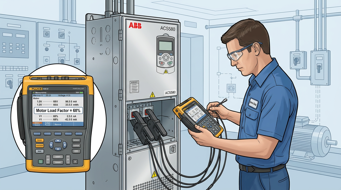
When an engineer walks past a 100 kW motor driving a pump that's throttled at 30% flow, the immediate thought should be: how much is this motor actually loaded? The answer lies in the motor load factor — a critical metric for efficiency, drive sizing, and energy cost reduction. Yet many plants in India operate with oversized motors running at 40–50% load, wasting power and shortening equipment life.
In this technical guide, we will show you how to calculate motor load factor step by step, using both theoretical formulas and practical measurements with instruments like Fluke power quality analyzers and ABB drive data. By the end, you'll be able to conduct your own motor audits and make informed decisions on upgrades, retrofits, or new drive selections.
What Is Motor Load Factor and Why Should You Care?
Motor load factor (MLF) is defined as the ratio of the actual power drawn by the motor to its rated full-load power. It is expressed as a percentage:
Load Factor (%) = (Actual Input Power / Rated Full-Load Power) × 100
But this simple formula hides a lot of nuance. A motor running at 60% load factor, for example, is operating inefficiently — the power factor drops, copper and iron losses become disproportionate, and the motor's temperature rise may actually be higher than at full load in some cases.
Why it matters in Indian industrial settings
- Energy costs: Industrial motors account for 60–70% of electricity consumption in many plants. A motor running at 50% load draws almost the same power as at 80% load but delivers half the mechanical work. Correcting load factor can save 5–15% on the motor's electricity bill.
- Drive selection: When sizing a variable frequency drive (VFD), overloading is a risk if the load factor is misinterpreted. ABB's ACS580 and ACS880 drives have built-in motor load measurement, but you need to understand the data.
- Commissioning support: Many engineers request a motor audit before installing a new drive. Knowing the actual load factor helps choose the correct heavy-duty vs. normal-duty rating.
The Formula: How to Calculate Motor Load Factor Step by Step
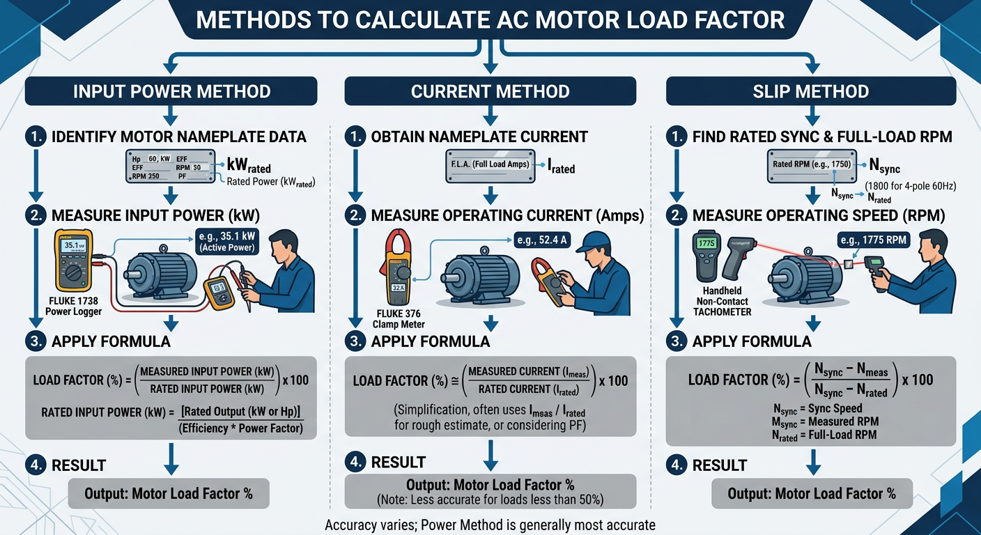
There are three common methods to determine the load on an induction motor. Each has its own accuracy level and equipment requirements.
Method 1: Using Input Power (Most Accurate)
This is the method recommended by ABB and Fluke for field audits. Measure the real electrical power (kW) at the motor terminals using a power quality analyzer or drive data.
Formula:
Load Factor (%) = (Measured kW / Rated kW at full load) × 100
Where:
- Measured kW = three-phase real power (P = √3 × V × I × PF)
- Rated kW = nameplate full-load power (converted from HP if needed: 1 HP = 0.746 kW)
Example: A 30 kW motor on a centrifugal pump draws 18 kW when measured with a Fluke 435 II. Load factor = (18 / 30) × 100 = 60%.
Method 2: Using Current Measurement (Approximate)
When only a clamp meter is available, motor load can be estimated from current. This method assumes rated current equals full-load current, but it ignores power factor variations.
Load Factor (%) ≈ (Measured Current / Rated Full-Load Current) × 100
This is less accurate because magnetizing current stays constant. A motor drawing 70% current might actually be at 50–60% load. Use this only for rough screening.
Method 3: Using Slip Measurement (For Commissioning)
Slip (the difference between synchronous speed and actual rotor speed) is directly proportional to torque. Measure the actual RPM with a tachometer, then:
Load Factor (%) ≈ (Measured Slip / Rated Full-Load Slip) × 100
This method is non-intrusive but requires access to the shaft and a tachometer. It works well for induction motors under steady load.
Tools for Measuring Input Power: ABB Drives and Fluke Instruments
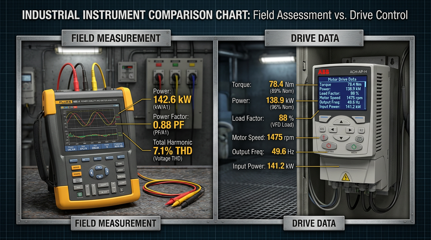
To calculate motor load factor accurately in the field, you need reliable instruments. Here's what Digital Controls recommends and supplies.
Fluke Power Quality Analyzers
- Fluke 435 II / 438 II: Three-phase power and energy analyzers that measure kW, kVA, power factor, harmonics, and motor energy. They can log data over hours to capture load variation.
- Fluke 377 FC / 378 FC: Clamp meters with iFlex current probes that measure true-rms current and voltage, giving you kW direct reading.
- Fluke MDA-550: Motor drive analyzer specifically designed for VFD-fed motors — measures DC bus ripple, PWM waveform, and motor shaft voltage.
Using a Fluke 435 II, you can measure real power (kW) at the motor terminals with ±0.1% accuracy. This is the gold standard for load factor calculation.
ABB Drives with Built-in Measurement
Modern ABB drives such as the ACS580, ACS880, and the new compact ACS180 have built-in motor control platforms that report actual motor torque, power, and efficiency. You can read these values via:
- The ACH-AP-H Assistant Control Panel
- Drive Composer software
- ABB Ability™ cloud platform
When a drive is already installed, you don't need external instruments. The drive's internal current and voltage sensors, combined with the motor model, give you the exact load factor in real time.
For plants considering a Variable Frequency Drive upgrade, Digital Controls can supply Fluke instruments for baseline audits and help configure ABB drives to log load data.
Pro tip: Always perform measurements under stable, normal operating conditions. Avoid transient states like starting or stopping.Explore our Fluke product range for field instruments.
Interpreting Load Factor Results: Efficiency and Drive Sizing
Once you have the load factor number, the real work begins. Here's how to interpret it for practical decisions.
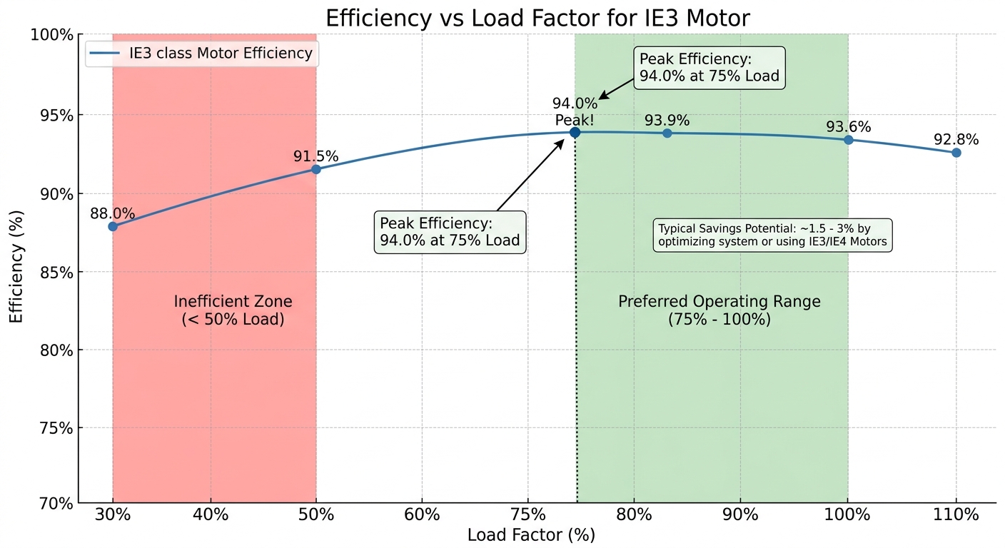
Efficiency vs. Load Factor Curve
A standard induction motor has peak efficiency at 75–100% load. Below 50% load, efficiency drops sharply. For example:
| Load Factor | Typical Efficiency (IE3 motor) |
|---|---|
| 100% | 95% |
| 75% | 95.5% (peak) |
| 50% | 93% |
| 30% | 87% |
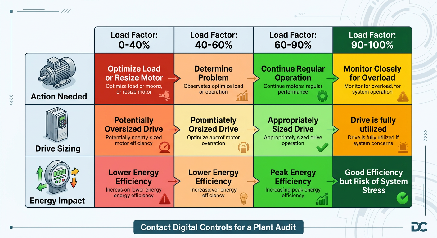
If your motor load factor is below 50%, consider:
- Replacing the motor with a smaller, properly sized one.
- Adding a VFD to match speed to load (especially for fans and pumps).
- Changing the driven equipment (e.g., trimming impeller, reducing pressure).
Drive Sizing: Constant Torque vs. Variable Torque
ABB's unified ACS180/380/580/880 family includes both Normal Duty (variable torque) and Heavy Duty (constant torque) ratings. The load factor tells you which duty cycle to choose.
- Load factor > 90%: Heavy duty — use a drive rated for 110% overload.
- Load factor 60–90%: Normal duty — standard drive selection is fine.
- Load factor < 60%: Oversized application — you may be able to use a lower current drive if the motor is already oversized.
For example, a 30 kW motor running at 40% load factor (12 kW) could be paired with a 15 kW drive if you plan to replace the motor later. But a cautious approach is to keep the drive rated for the existing motor's full-load current to allow future changes.
Our technical team at Digital Controls provides application review and control panel coordination to ensure your drive and motor combination is optimized for actual load.
Common Mistakes and Best Practices
Even experienced engineers can mis-calculate motor load factor. Here are pitfalls to avoid.
Mistake 1: Using Nameplate Current as Full-Load Current
The nameplate current is for full-load at rated voltage and frequency. If supply voltage is (say) 415V instead of 400V, the actual full-load current changes. Always use the motor's actual full-load current from its performance curve or datasheet, not just the nameplate.
Mistake 2: Measuring Unbalanced Voltage
Three-phase unbalance of even 2% can cause a 5–10% increase in current without increasing real power. The Fluke 435 II will show negative sequence components — correct those first before trusting the kW reading.
Mistake 3: Ignoring Harmonic Content
With VFDs, the current waveform is non-sinusoidal. A standard clamp meter may read RMS current incorrectly. Use a Fluke with true-rms and harmonic analysis, or read kW directly from the ABB drive.
Best Practices Checklist
- Measure kW at motor terminals, not at the distribution panel (cable losses distort readings).
- Log data over at least one full operating cycle (e.g., 24 hours for pump with variable flow).
- Record voltage, current, power factor, and THD alongside kW.
- For compliance reporting, use instruments with current calibration certificates.
For a full plant motor audit, consider our motor audit and commissioning support — we bring Fluke analyzers and ABB configuration tools.
Frequently Asked Questions
How often should I calculate motor load factor?
For critical process motors, perform a load factor audit quarterly. For standard pump and fan motors, an annual measurement is sufficient, especially if load conditions are stable. Any time a VFD is added or a motor is replaced, recalculate.
Can I calculate load factor without a power analyzer?
Yes, using the current approximation method gives a rough estimate (±15% error). But for drive sizing and energy efficiency projects, a kW measurement is strongly recommended. Digital Controls can loan Fluke instruments for trial audits.
What is a good motor load factor?
For a standard squirel-cage induction motor under steady load, a load factor of 75–95% is ideal. Below 60%, consider upsizing or using a VFD. Above 100% indicates overload — reduce load immediately to avoid thermal damage.
How does load factor affect power factor?
As load factor decreases, power factor also drops. A motor at 50% load may have a PF of 0.6–0.7, causing higher reactive power demand and penalty charges. Adding a VFD or capacitor bank can improve overall plant PF.
Conclusion: Turn Data into Action
Knowing how to calculate motor load factor is the first step toward energy efficiency, better drive selection, and reduced downtime. Whether you use a Fluke power analyzer for spot measurements or an ABB drive's built-in data, the numbers don't lie.
At Digital Controls, we don't just sell instruments and drives — we help you apply them. From proving your motor is undersized to selecting the right ACS580 heavy-duty drive, our team provides the engineering support Indian plants need.
Contact our experts for a motor audit or drive selection consultation. We'll help you calculate motor load factor across your entire plant and recommend cost-saving upgrades.
Related reading: ABB drives product range | Three phase induction motor basics | Energy efficiency solutions